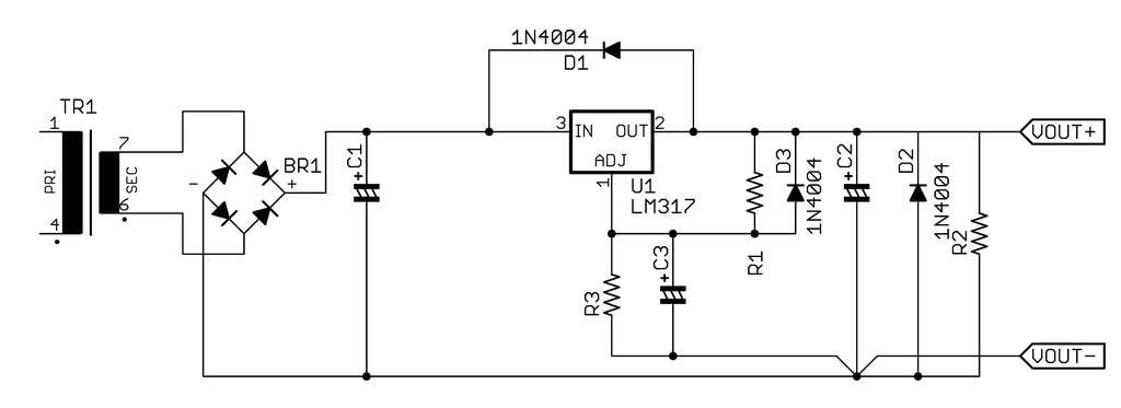
The voltage across C1 is (approx) 1.414 * the AC secondary voltage. This is higher than the output voltage by enough to overcome the regulator's Vin-Vout limitation, for most instances. Your low-line performance may not be what you expect. Making C1 larger can help. The important thing is to ensure that when the circuit is driving its rated load, the lowest voltge across C1 is still above the Vin-Vout minimum. You need to look at the voltage with a scope to see the waveform.
If you raise the secondary voltage, there is more voltage across C1, but also more voltage across the regulator. The regulator has no choice but to turn it into heat, which you have to get rid of via a heat sink. If the regulator dissipation is low enough, then you get to omit the heat sink.
See #1.
The object here is to keep the ripple current from the transformer/rectifier/filter system confined to just that. Ripple currents can be high enough that the voltage drop caused by conductor resistance can affect things downstream.
You may need to create some sort of soft start circuit like a resistor between BR1 and C1. This limits the charging current and forces C1 to charge more slowly. A relay or FET in parallel with the resistor shunts the resistor after an appropriate time period (a few seconds).
This is very important, and is the reason for making the transformer's secondary voltage AT LEAST equal to the desired DC output voltage. See #8.
The local bypass should be a capacitor with good HF characteristics, like a monolithic ceramic. 100nF is sufficient. It needs to be right at the regulator.
Refer to the regulator's data sheet for more detailed information.
Refer to the regulator's data sheet for more detailed information.
Refer to the regulator's data sheet for more detailed information.
P = E^2/R. The resistor should be rated at least 2x this amount.
Diodes are cheap insurance. Regulators less so. Don't Muntz these out.
Refer to the regulator's data sheet for more detailed information.
Refer to the data sheet.
If in doubt: make the heat sink bigger. You can use your handy bio-digital thermometer (your thumb) to check the case temperature. If your thumb really doesn't want to be there, then you need more heat sink.
Last modified 07/27/2018.