The Loudspeaker System
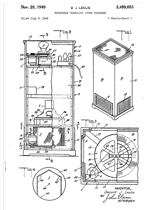
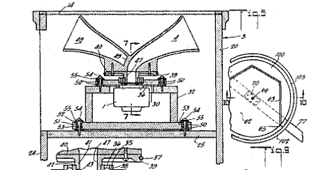
There are two basic Leslie Speakers (Leslie) found in common use today: The model 122 and the model 147. They differ in size as well as in the amplifier configuration. Both use the same speaker components, a 15" speaker of no particular provenance, and a phenolic dome compression driver fitted to a rotatable horn. Rather than attempt to rotate the 15" speaker, it is mounted above a rotating drum having an angled baffle that "sprays" the sound in a 360-degree arc when the drum is rotating. A simple 2-pole (12-dB/octave) crossover divides the signals to the two loudspeakers.
Shaded pole AC motors drive the rotors, with a separate motor for each unit. Some of the motors are two speed, but the majority found are single speed. The motors are under control of the musician, and controlled together. The motors are not just turned on and left, rather, they are played by the musician, to control their speed via duty cycle; sometimes they are just pulsed on and off, left to coast to a stop, etc. There is a particular sound imparted as the rotors accelerate, and this is often used to good effect.
There is no attempt made to synchronize the rotation of the two moving systems (their masses are different). Although each system gets started at the same time, because of the mass differences, each accelerates to its final speed at its own rate, and when the motors are shut off, each decelerates at its own rate.
The Amplifier System
The model 122 speaker is typically connected to a Hammond B or C series organ console. The 147 is usually found connected to the spinet organs such as the M100 or L100. Both amplifiers have the same general circuit and power output, but differ in the topology of the input and in how the motor switching is accomplished.Each amplifier has a pair of 6550 beam pentodes and a 12AU7 that operates as a push-pull driver (122) or as a long-tailed-pair phase splitter (147). The output stage has cathode feedback (sometimes) from the output transformer's speaker winding, which is center-tapped. The amplifier is cathode biased and delivers about 60-watts to the load. In days past, the Leslie was regarded as being somewhat wimpy (lacking in acoustic output) and all make and manner of modifications sprang out of this. Some of these modifications/solutions were:
- Multiple Leslies
- Clipping the deflectors out of the horns.
- Changing the speakers to JBL or Altec units.
- Modifying the amplifier (fixed bias)
- replacing the amplifier
- etc.
With the advent of multi-miking instruments for sound reinforcement, the complaints about the Leslie's lack of acoustic output disappeared. The 122 amplifier has the following connections to the Leslie Cable.
- Balanced input
- Ground
- 120VAC
- 120VAC
- 310V DC Source (thru 10k)
- Balanced input


Drawings taken from the original Leslie patent.
The 147 amplifier has the following connections to the Leslie Cable.
- Ground
- Relay Coil
- 120VAC
- 120VAC
- Relay Coil
- Amplifier Input
Amplifier Schematics
Leslie and Hammond SchematicsThe Total System
The Leslie's unique sound, especially when combined with a Hammond organ and a player who has figured out the nuances of this total instrument, are particularly musical and suited to many different musical genres (arguably rock, blues, and jazz most often make use of this). Probably the most definitive sound is the way that the amplifier and speakers overload when overdriven, especially in the bass region. The power amplifier overloads particularly gracefully and musically, and this produces a very pleasing roundness of tone. Skillful use of the expression pedal and the bass pedal notes adds to the effect, especially when the amplifier is driven into clipping (distortion). In addition, the bass clipping causes intermodulation distortion that modulates the higher notes being played, making them (in the extreme) gargle.The total effect of the moving sources makes synthesizing the sound particularly difficult; a great deal of effort has been expended in trying to make an effect pedal that emulates a Leslie. Because of the amplifier and speaker system's unique overload characteristic, replacing the amplifier with something more powerful and/or replacing the speakers with more powerful components is usually less than satisfactory. Electro-Music (the CBS division that produced the Leslie) tried wrapping this into a single package with the 900 series cabinets. These had solid state amplifiers and used JBL components, but because CBS (apparently) didn't understand the unique synergy of the 60w tube amplifier and the plain vanilla speakers, these units only found favor when the only judgment criteria was sheer volume. Because of the solid-state amplifiers, however, these units were not at all musical when played into overload.
The Motor Drive System
The motors used are small shaded pole AC motors. There are four: two per rotor, two per speed. They require 120VAC for operation. They are switched, in pairs, via a single SPDT relay.- In the 122 amplifier, the signal to control the speakers is a DC voltage sent equally on the two audio wires (it is common mode, and the amplifier's balanced input ignores it). This signal is applied to the relay control tube, 1/2 of a 12AU7, and biases it on (+DC) or off (ground, 0V). The tube's plate current operates the relay. The tube is biased by the cathode voltage of the output tubes (25v), and with no control signal, the tube is cut off, the relay is open, and the rotor motors run at high speed. 25V should be enough voltage to bias the tube on; in effect this is 0 bias, closing the relay and switching the rotor motors to slow speed.
- In the 147 amplifier, the relay has its own pair of wires in the Leslie cable. The relay requires 120V AC for operation.
The Interface
There are two parts to this:- Amplifier drive
- Rotor drive
The 122 Leslie
The simplest way to drive the 122 amplifier is to put some sort of 1:1 transformer between the amplifier input and the source. This is especially true if you are using the Leslie cable as a way to get signal to the amplifier. If you want rotor (motor) control, then use the 295V source at pin 5 to derive a lower voltage (about 25v) and switch this to pins 1 and 6 simultaneously. It would be a good idea to put a short time constant on this voltage as it is applied to the signal lines. If the transformer is center-tapped, this is a convenient way to apply the common-mode control voltage. Supply power for the Leslie across pins pins 3 and 4. Treat this with respect. Be sure that your audio wiring is sufficiently isolated from this.
If reading this description isn't crystal clear to you, then you don't know enough to do this without endangering your own life or someone else's. Find a competent tech who can read this description and follow it, and have them do the work. Because of this life safety issue, I reserve the right to refuse questions on this topic. This is not the time to be P.C. or polite.If I don't think you know what you're doing, I'm not going to help you kill yourself.
If it's too much trouble to derive the voltage for rotor control, and you just want the leslie effect, then unplug the high-speed or low-speed rotors from the amplifier and power them from an extension cord.
DIY 122 Interface

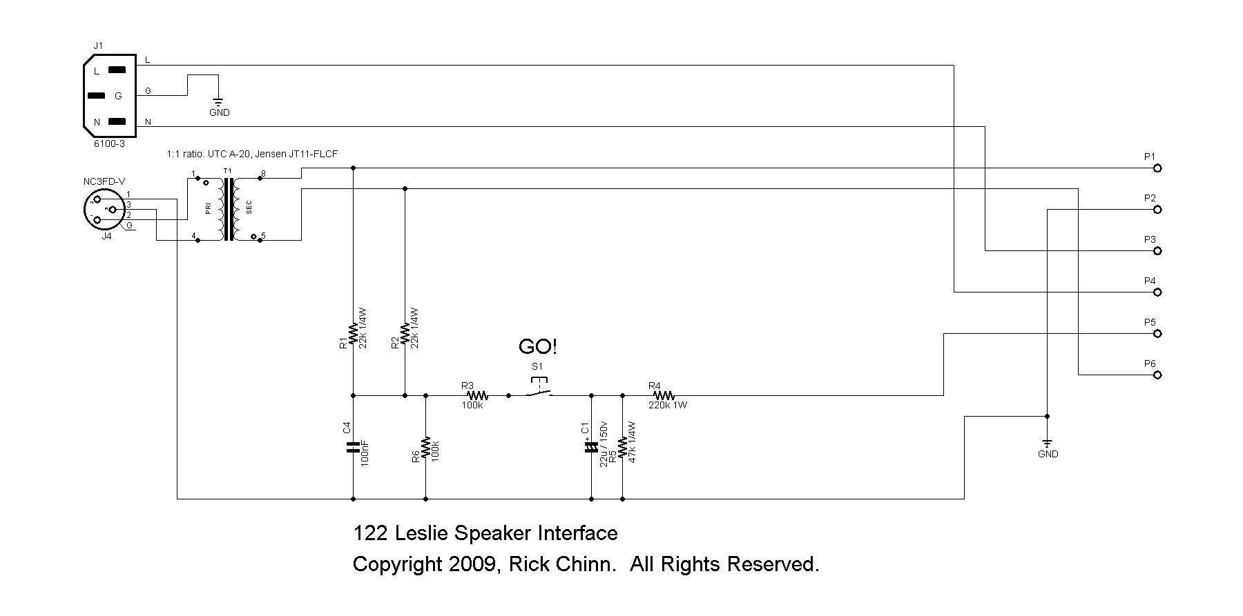
This circuit allows driving the 122 Leslie's amp from a balanced line level source. I don't really know the sensitivity, but +4dBu ought to get the job done.
In the circuit, T1 ensures that there is balanced drive to the Leslie amp. R1 and R2 apply the common-mode DC control signal to the signal lines. R3, R6, and C4 ramp the control signal to minimize clicks at the moment of enabling the relay. R5 and R5 make a 6:1 voltage divider to take the 310v down to about 50v. C1 filters this, just to be sure. S1 connects the 50v source to the time constant network and then to the signal wires.
If you wanted a footswitch sort of thing (footswitch plugs into the interface box), then wire S1 as a short circuit, turn R3 into two 47k resistors, and wire the footswitch to short their junction (midpoint) to ground. The sense of the circuit is that the rotors run fast when the midpoint is shorted.
T1 can be just about any sort of 1:1 audio transformer. The schematic suggests a UTC A20 or Jensen JT13-FLCF. A UTC A21 will also work, with the advantage of being magnetically shielded. I think when I built one of these 30 years ago, I used a Triad A67J. The UTC and Triad parts can be found on Ebay, and the Jensen part is available from Jensen Transformers. www.jensentransformers.com
Permission is granted to use this circuit for your own, non-commercial, purposes. If you want to build it for someone else once or twice, that's fine. Beyond that, we should talk about it.
The 147 Leslie
This amplifier, because of the unbalanced input, is a bit more problematic to drive. Because of the presence of 120VAC within the Leslie cable, you need a low-source impedance to drive the input to help guard against hum. Again, a 1:1 transformer is advised simply to add a degree of isolation between the external audio system and the 147 amplifier input. In this case, set the impedance switch to OPEN, which makes the input impedance 10k. If you make a special cable, so the audio input to the amplifier doesn't run alongside the 120V AC power, then you may be able to get past having to use a 1:1 audio isolation transformer at the input. Again, set the switch to OPEN, and connect to pins 1 (gnd) and 6 (signal). Keep in mind that 120V from the power line is on pins 3 and 4, and you should treat this with an appropriate amount of respect.
If reading this description isn't crystal clear to you, then you don't know enough to do this without endangering your own life or someone else's. Find a competent tech who can read this description and follow it, and have them do the work. Because of this life safety issue, I reserve the right to refuse questions on this topic. This is not the time to be P.C. or polite.If I don't think you know what you're doing, I'm not going to help you kill yourself.
You can also use a small guitar amp to drive the 147. Set the input impedance switch to 8-ohms. Connect the guitar amp to pins 1 (gnd) and 6 (signal). Make sure the amp is small, a pair of 6V6 or EL84 or less. If you want to use something bigger, either connect it directly to the Leslie's speakers, bypassing the Leslie amplifier or use a power attenuator as a dummy load and set the Leslie's input impedance switch to OPEN. Remember that any amplifier much larger than the original Leslie amp will get louder, but it will also more than likely wipe out a speaker or driver in the process. Specifically, distorted guitar at high levels with more than a 60W amplifier behind it is a pretty good guarantee that your Leslie will fail on you.
The details of the 147 Leslie interface are left as an exercise for the interested student.
A Bit More
Here are links providing more information, either about the Hammond Organ or the Leslie Speaker. C. R. Lester's pages about Don Leslie,
including the story of the Leslie Speaker. (used with permission)
Hammond History Page
Hammond B3-C3 Harmonic Percussion
circuit is described here.
Hammond B3 schematic diagram.