The Voltage Divider
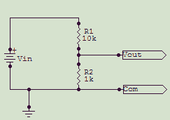
If you've ever studied electronics, then perhaps you studied and solved the voltage divider equations. Refer to the schematic for the L pad. In class, they probably stacked the resistors vertically, one above the other. You can analyze this circuit two different ways, getting the same answer at the end.Generally, the solution method taught for voltage dividers was based on Ohm's law, which works every time, but sometimes isn't the easiest way to wrap your brain around the problem.
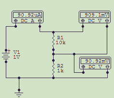
Using Ohm's law, calculate the total current in the circuit. It's the applied voltage divided by the sum of the resistors:
It = E/Rt = 1/(10k+1k) = 1/11k = 90.9 microamps.
In a series circuit, the current through the circuit is the same at any node (Kirchoff's law). The voltage drop across any resistor in the loop is equal to the current through the resistor times the resistance:
ER1 = ItR1 = 90.9µA * 10k = .9091V
ER2 = ItR2 = 90.9µA * 1k = .09091V
Finally, as a check, Kirchoff's law also says that the sum of the voltage drops in a circuit equals the applied voltage:
ER1 + ER2 = .9091 + .09091 = 1V
Now look at the circuit from the standpoint of the ratios of the elements. The applied input voltage will be divided by a factor of 1 plus the ratio of the elements.
You can visualize this easily with a simple 1:1 divider; two equal-value resistors. By inspection you may already know that the input voltage will be divided by two. The ratio of the two resistors is 1. The attenuation ratio is the resistor ratio 1 plus 1 = 2. Revisiting the 10:1 voltage divider:
Eo = Ein / k, where k is the attenuation ratio, or 1+(R1/R2).
k = 1+(10k/1k) = 11
Eo = 1/11 = .0901V
Vin/Vout = (R1+R2)/R2 = R1/R2 + R2/R2 = 1+(R1/R2)
finally, solving for Vout:
Vout = Vin/(1+(R1/R2))