A process for transducing acoustical signals, including music, speech, noise, etc. which embodies a method which eliminates the usual discrimination between the frequency spectra of the direct and random incidence acoustical components of the sound being transduced and allows the frequency range of interest to be controlled by adjusting the spacing between the diaphragm or major entry port of an acoustical to electrical transducerIn short, the big benefit was the elimination of comb filtering caused by sound arriving via reflections from nearby surfaces and sound arriving directly. Ken Wahrenbrock licensed this idea and produced the first commercially available microphones using this idea. Eventually Crown International (you know, the guys who brought you the DC300 amplifier) purchased the trademark and license and they produce microphones using the Pressure Recording Principle to this day.
You'll note that the patent expired in 1999, however Crown still owns the trademarked terms, "PZM and Pressure Zone Microphone."
The Radio Shack™ PZM™ Microphone
Many years ago, Radio Shack (RS) sold a Pressure Zone Microphone, models 33-1090, 33-1090A, 33-1090B under license from Crown International. These were an inexpensive alternative to the Crown product and worked OK. Not great, but OK. Oddly, RS told people in the manual that by substituting a higher voltage battery they could improve the performance of this modest microphone. Many tapers have gone this route, and while it does improve performance, there are still a few limiting factors: the puny output transformer, the non-standard output impedance, and the battery.Some time later, RS decided (or perhaps Crown decided for them) to no longer sell the PZM microphone and came up with a replacement called a Boundary Microphone (getting past the trademark), model 33-3020. Unlike the PZM which uses an omni capsule mounted a fraction of an inch away from a boundary surface, the RS Boundary microphone uses a microphone capsule mounted 90 degrees to and adjacent to a boundary surface, much like the EV mike mouse. This model suffered the same limitations as the original unit AND it was wired differently. Later yet, RS replaced that model with yet another, model 33-3022. This too is called a Boundary Microphone and looks totally different than the previous unit. Unlike the #1 and #2 units, this had no output transformer. Instead it had an output choke, whose purpose is to short out any electret microphone bias present at the input, as it would be if the microphone were plugged into a consumer camcorder.
Sometime around 2008, RS dropped the 33-3022 unit and introduced their 33-3041 Business Microphone. This is not a boundary microphone nor is it a PZM. It is an omni electret capsule mounted so it is sticking up in the air. If you snip off the battery box, it conforms to the Configuration 2 wiring. RS also sells a boundary microphone made by Audio Technica. The information on their website is insufficient to even infer any details.
The 33-1080 Microphone
We originally thought this was a PZM, and the RS website would lead you to believe that, but came to find out that the 33-1080 is NOT a PZM, it's a conventional probe-style cardioid microphone. Here's the datasheet for the 33-1080. A special thanks to MichaelD in the UK for bringing this to my attention.Modifications Galore
Several people have published modifications for this microphone (models 33-1090, 330-3020). All are aimed at making the things compatible with standard professional low-impedance balanced inputs, with or without phantom power. The easy modification is cutting the 1/4" phone plug off and rewiring the leads to a male XLR connector. The output of the first two models was balanced by virtue of the output transformer. Do this and add the 12V battery and you've already improved things. It still doesn't know a thing about phantom powering. The puny output transformer remains, and it has less magnetic shielding than your middle finger (and about as much iron, maybe less considering your blood). It is common to hear people complaining of hum.In the 1970s Phil Rastocny published a modification that has gotten more than a bit of attention. It is probably the origins of the "put a bigger battery in" modifications. Phil's mod changes the battery to 9V and raises the value of the load resistor to 2k2. He also gives the nasty little transformer the heave-ho. When you're done, you have a fairly vanilla electret microphone with an unbalanced output, unsuitable for connection to a balanced microphone input.
Christopher Hicks published a clever circuit that lets the microphone drive a balanced input. Chris' circuit puts the microphone element across the phantom powered input and uses a pair of PNP transistors running as emitter followers to drive the line. Our objection to this circuit is its total dependence on the CMRR of the balanced input as neither side of the microphone element is grounded; you must replace the cable with 2C shielded twisted pair. That means that you get to solder the new wires to the microphone element, which is risky business at best, unless you have mastered the Art of Hit and Run Soldering.
We mention all of these other approaches to provide some history and background. Some time ago, around 1994, tired of all the hoopla about these mikes, these less-than-complete modifications, and tired about endless questions about operating them in a P48 environment. We designed our own interface for these microphones that was to end the problem and make a definitive step forward towards a totally professional interface. The goals were straightforward:
- Get rid of the battery, run the thing from the P48 supply
- Lower the distortion
- Get rid of that nasty little transformer to improve the bass response and reduce the sensitivity to hum fields.
We posted the circuit to one of the forums on Compuserve, and later put it on our website. A kind soul on Compuserve (IvanF) did a PCB layout of the design and sent a couple of panels of boards. At the time, RS was selling the -1090 model, which ran the capsule "upside down" both physically and electrically. (The physically upside down capsule was part of the patent.)
When RS introduced the newer -3020 model, we bought one and found that it was electrically incompatible with the original interface design because this one ran the FET in the microphone as a common source amplifier, whereas the older -1080 and -1090 models ran the FET as a source follower. We intended to find a way to use the original circuit boards with the newer model, but as these things go, never got around to it, and finally, RS had replaced the -3020 with the -3022 model. A look at the -3022 model revealed that this model was very different, and the modifications of days past were no longer applicable. About this time, orders started coming in for a kit available from Uneeda and the stock of original boards ran out. This was a perfect excuse to redesign the circuit board and to make it compatible with all models.
Someone once said that a picture is worth a thousand words, so here are some pictures to help you identify the different models.

|

|

|

|
|
The original RS PZM, model 33-1090B.
Config 1 |
The 33-3020 model Boundary Microphone.
Config 2 |
The boundary microphone, the 33-3022 model.
Config 2 |
The 33-3041 Business Microphone. (whatever
that
means.
Config 2 |
The New RS PZM Board
Kit manual (5MB pdf) Prices and Ordering info Photos Troubleshooting TipsThe new circuit differs from that previously shown on the website. The new circuit can be used:
- With the 33-1090, 33-1090A, 33-1090B licensed products from Crown. These units have the tradename PZM marked on the boundary plate.
- With the 33-3020 and 33-3022 boundary microphones.
- With the 33-3041 business microphone.
- With generic electret capsules, such as those made by Panasonic.
The different circuit configurations are realized by jumper wires on the PCB. There are stuffing arrangements to accommodate the different applications (the -3020/3022 microphones and the generic electret capsule take the same configuration).
The transformer inside the -1090 battery box loses about 3 dB of signal (by design), so when this microphone is modified, the output signal is about 9 dB hotter than it was before. The small size of the transformer also limits the low-frequency response; eliminating it removes the LF rolloff associated with the transformer and it's contribution to the harmonic distortion performance. If that isn't enough, the transformer is magnetically unshielded making it a very effective hum magnet.
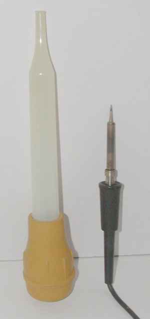
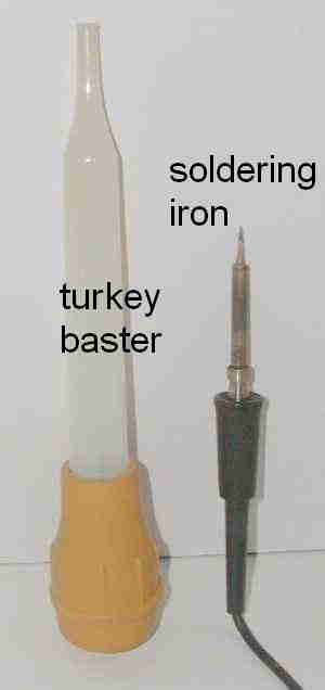
We put together a semi-kit of parts with the new board and all of the electronic components needed. There's instructions now, and it even includes some small-diameter solder (USA only). This is still not a job for a rank amateur, and if you don't know the business end of a soldering iron from a turkey baster maybe this isn't for you. The instructions and pictures can be found here. (5MB pdf)
The semi-kit is $75USD postpaid to any USA address. Other destinations are the same price, but postage is extra; please inquire first. We accept payment via PayPal.
n.b. New import regulations in the EU and Canada asses value-added tax, duty, and/or fees on incoming parcels. We don't know if this is all of the EU or just certain countries.
Here's the notification that we got at USPS when shipping a kit and project box to France. The amount is not trivial. You are responsible to pay this (if levied) when you receive the parcel. We think this is an answer (retaliation?) to the US removing the de minimus exemption for parcels worth less than $800usd. Or maybe it is the other way around. Whatever, at the moment, as the purchaser, these fees are yours to bear.
The kit is called a semi-kit because it includes everything that you need to assemble the printed circuit board but does not include a case, or the connectors. See the price list for other options. It does include:
- the circuit board
- all resistors and capacitors
- the ferrite beads
- all of the semiconductors: diodes, transistors, and the transistor array
- spacers and mounting screws
- 63/37 tin/lead solder if you are in the USA or Canada.
The case needs to be made of metal, for shielding reasons. If you use the recommended Hammond box, all of the holes can be drilled, although the 3/4" hole for the large XLR connector can be difficult. I use a Greenlee chassis punch. You can also use a Unibit stepped drill bit. Yes, you can get 3/4" drill bits, but even with a drill press, they are unwieldy and even a bit dangerous. NOT recommended.
You can purchase a project box with the 3/4" hole pre-punched. The rest of the holes are yours to drill.
Even after all this work, remember the microphone's humble beginnings. It will never ever be a Neumann, but it will be substantially better than it ever was. Refer to the audio samples referenced in the menu at the beginning of this webpage.
RoHS
In July 2006, EU member states adopted a set of rules governing nearly anything electronic aimed at curtailing the presence of hazardous substances in landfills. These rules are known by their acronym RoHS (Rules of Hazardous Substances). For electronics, the primary banned substance is lead, which is a component in tin-lead solder. Not only must electronic equipment use lead-free solder, the components used must also be free of lead. In the United States, California is on the edge of adopting similar legislation. It is just a matter of time for other states.The kit is considered a repair component because it extends the life of a non-compliant article that was placed on the market prior to 1 July 2006. By Article 2 Section 3 of the Directive, repair parts are exempt. If you are hassled by customs because of RoHS, then point out that this is a repair part, which is exempt. Regardless, we are attempting to comply because nearly all of the components are RoHS compliant. Solder is not included when shipping outside of North America.
For more information, refer to this (courtesy of Newark Electronics) and this website's RoHS Page.
Once again, since the kit is used to maintain the usefulness of a non-RoHS product (by keeping it out of the landfill), the kit is considered a repair part, and as such, it is exempt from RoHS rules. So as to not tweak the bear, solder is not included with kits shipped to the EU.
n.b. If you are in the EU and you ask nicely, we can supply a length of lead-free solder, however this is a possible sticky wicket because the solder will just be contained in a polybag with nothing to prove to customs that it is lead free. We think it's safer to not tweak the bear.
The same discussion applies to pre-assembled kits that are shipped to the EU.
License
NOTE: No license is granted with respect to this circuit. Permission is hereby granted for you to construct the circuit and use it for your own use. Permission to use this circuit in a commercial context (i.e. turn it into a product for sale) is not granted. Purchasing a kit from Uneeda Audio grants you a per-instance license to construct/use/sell the item using that instance of the circuit.
Here's What You Need
Price List and Ordering InfoBe sure to refresh/reload this page to ensure that you're getting the latest version.
The kit, and just the kit, fits into a padded envelope, and that costs the least to mail (important since the price includes postage). The chassis boxes weigh more, and they will push the shipping price up. International mail is much more, and is driven by weight and parcel dimensions. If you must have package tracking and a non-US address, it will cost a great deal more. All international destinations (including Canada) ship via USPS only. The rest are far too complicated for ordinary humans (us). USPS now has tracking by default for domestic mail. Washington State residents must pay retail sales tax, which is based on the delivery address. For a price, we can supply completely assembled preamps, made to your order. This usually takes about 4-weeks. See the price list for more details. To order:
|
|||||||||||||||||||||||||||||||||||||||||||||||||||||||||||||||||||||||||||||||||||||||||||||||||
Yet More Stuff
Here are some pictures of the raw boards, completed boards, and a completed preamp. Remember that when you buy the kit, the cool metal case is not part of the deal. The metal case is made by Hammond (p/n 1590BBK) and it can be purchased pre-painted. In the picture of the completed unit, the output connector (larger) is on the left and the input connector (mini-xlr) is on the right.One of the completed boards shows phoenix connector blocks mounted on the board. These are an alternate way to get the wiring off of the board. They are not included in the kit. They are $3.50 each if they are ordered with the kit.
Click the pictures to enlarge them. The boards shown here are the original Rev C boards. The new board, Rev F1 looks substantially the same, except that the LM394 is replaced with a THAT 300P quad transistor array. The manual for Revision F1 shows the new board. The changes for Revision F1 were mechanical.

Revision F1 PCB |

configuration jumpers |

Completed and packaged preamp. |

note: rev C board |
The 2020 (latest) revision for the Revision F1 PCB.
Troubleshooting Tips
Christopher Hick's mod
Phil Rastocny's mod
Back to Uneeda Audio
The construction manuals for Revisions A, B, C and F are available upon request.
Copyright 2003-present by Rick Chinn. All rights reserved.